Get Started with Altium Upverter, Sign Up Now.

Ethernet is the traditional technology for connecting wired local area networks (LANs), allowing devices to communicate with each other via a standardized protocol. Since it is a local area technology, it is used mostly for networks operating within a single building. You can use Ethernet to connect your new board to the internet, where you have the freedom to save, retrieve, and visualize your data in a browser.
For some designs it is essential to have some level of remote connectivity for data transfer, monitoring, and sometimes for firmware upgrades. Connecting your project to a LAN allows you to tunnel into your board via SSH and modify software when required. Adding Ethernet to your board requires following some particular routing standards and choosing the correct parts for your board.
Design Considerations for Ethernet
Low cost PLDs, like simpler FPGAs and MCUs, typically need to communicate with an external Ethernet controller via SPI. This external controller provides medium access control (MAC), which is governed in its own firmware, and it acts as the physical layer (PHY). This integrated MAC/PHY then connects to the RJ45 connector using a standardized routing scheme. This is shown in the image below.
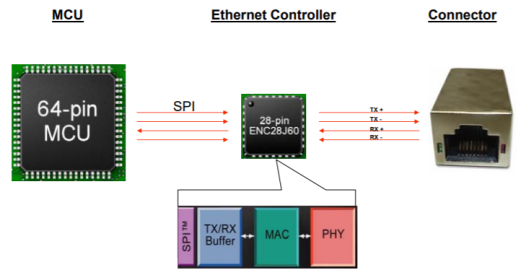
Ethernet controller for connecting your device to Ethernet [Image source]
Although the MAC and PHY blocks can be integrated into an external Ethernet controller, some newer MCUs include their own integrated Ethernet controller. This means you won’t need to use an external controller IC. Make sure to check the specifications of your MCU/FPGA before searching for an Ethernet controller IC.
Some examples of Ethernet controller IC are the ENC28J60, W5100, W5500, and many others. The RJ-45 connector can also be packaged in a single device, known as Mag-Jack. Using one of these components eliminates the need to design your own magnetic termination circuit. It should be noted that the Ethernet protocol standards clearly state that you must use a transformer on the Ethernet port in order to provide isolation and to remove any DC bias on the signal.
The image below shows an example of a simple RJ-45 Mag-Jack breakout board. The connector on this board includes the magnetic termination circuit required to isolate the connector. This board can be easily soldered to a standard header on an existing MCU board or on a shield board.

RJ-45 Mag-Jack breakout board
When creating an Ethernet PCB layout, the designer needs to choose the maximum data rate, physical media (i.e., which type of cable), and duplex mode. In embedded systems design, one of the most common speed choices is a 100Base protocol (100 Mbps); anything faster is unnecessary as MCUs are not equipped to handle higher speeds. Going to a GBase (1 Gbps) protocol requires a faster processor and controller. Most development boards that include this level of processing power will already include Ethernet; BeagleBone Black and Raspberry Pi are great examples.
Sometimes, it makes more sense to use 10 Mbps, depending on the speed of other devices in your LAN. This will definitely bring a cost advantage, and you might not notice the difference in communication speed unless your network has heavy data traffic or you need to transmit large amounts of data to/from your device. For example, if you are implementing Ethernet external to the MCU, Microchip’s ENC28J60 10 Mbps Ethernet controller is slightly lower cost than their ENC624J600 100 Mbps controller.
Using Ethernet Shields
If you are working with development board like Arduino or Raspberry Pi, then this task becomes easier. Raspberry Pi already has an Ethernet port where you can directly connect the cable. Here is an excellent tutorial for connecting Raspberry Pi to Ethernet.

Connecting Raspberry Pi 3 Model B to Ethernet
Arduino doesn’t have a direct Ethernet port, but there are shields available on the market that you can connect to your Arduino board. These shields are basically Arduino-compatible boards that have similar layout and contain an Ethernet controller (either Wiznet W5100 or W5500), and an the RJ-45 Mag-Jack. If you are looking for something cheaper, you can easily find small Ethernet modules for around $10. These modules are small in size, but they have limited speed (10 Mbps). Before you buy one, make sure to check pin compatibility and voltage levels. There are a lot of libraries available that can be used and many examples to help get your design up and running.
Ethernet PCB Layout for Your Own Board or Shield
If the available boards do not suit your specification or you need to meet certain area (footprint) or power constraint, then you might want to design your own board or shield. Signal traces from the controller to the RJ45 connector should be routed as short as possible on a single layer, and traces should be routed in a straight path. Try not to bend a trace by more than 45 degrees.
If your MCU/FPGA does not include the PHY layer, and you are not using an integrated Ethernet controller, the MCU/FPGA will act as the MAC layer and will need to communicate with an external PHY IC to drive signals over the RJ45 connector. Routing between the MAC and PHY layers uses MII or RMII routing, depending on the speed you are working with. Once you understand how signals are triggered in each layer, it becomes rather easy to route traces between the various components.
Upverter® provides a great library of reliable components where you can easily find the parts you need for your Ethernet PCB layout. If you are looking for an Ethernet controller, you can find the ENC28J60, W5100, W5500, and other controllers in the parts database. You can find the SI-60062-F, J0011D01BNL, or JXD1-0001NL RJ45 connectors, all of which have built-in magnetics. Here is a great example of an Ethernet controller module with W5500, which you can use as a template.
As a cloud-based PCB design tool, Upverter gives users the ability to share their designs, control revisions, and store design data in a secure online repository which is accessible from any location. You can browse thousands of open-source designs in Upverter’s projects database and pick one to customize for your new design.
You can sign up for free and get access to the best browser-based PCB editor, schematic editor, and component database. Visit Upverter today to learn more.
